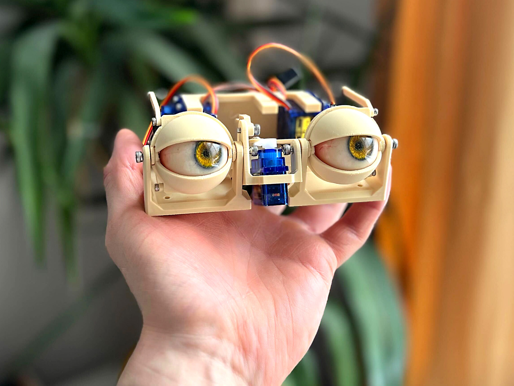
Simple Animatronic Eyes
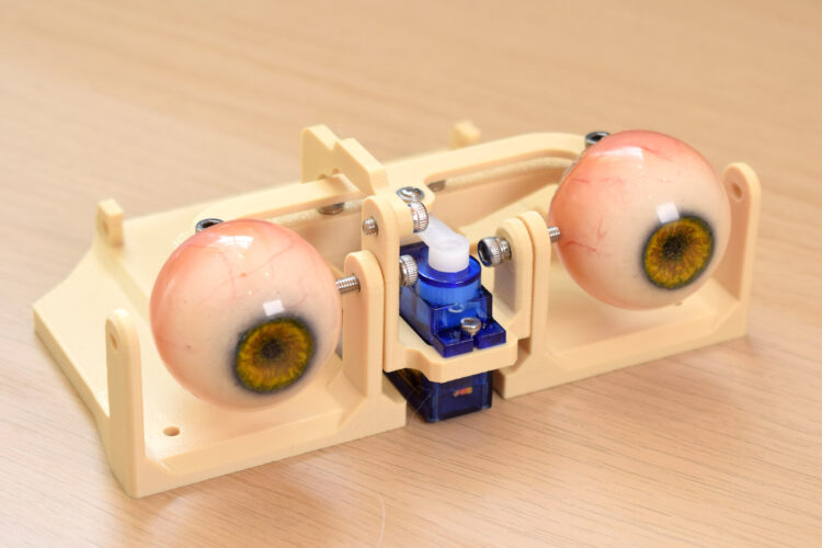
Build a realistic eye mechanism for live joystick control or automated projects! This project allows you to create animatronic eyes that can look left, right, up, and down, with eyelids that subtly follow the gaze. A button triggers a rapid blink. The eyes are controlled by an Arduino and can be integrated into larger projects like costumes, robots, or props.
Tutorial by Will Cogley . All credit goes to the original content author. View original source
Glossary
Technical terms and jargon used in this project:
- Servo
- A small motor that can be precisely controlled to rotate to a specific angle. Used here to move the eyes and eyelids.
- In this project: SG90 micro servos are used as actuators for the eye and eyelid movements.
- Arduino
- An open-source microcontroller platform used for building digital devices and interactive objects. It reads inputs and controls outputs like servos.
- In this project: The Arduino runs the code that interprets joystick and button inputs to control the servos.
- Servo Driver Board
- An expansion board that allows a microcontroller like an Arduino to control multiple servos simultaneously, providing power and signal management.
- In this project: A 16-channel servo driver board is used to control the six servos in this project.
- Potentiometer
- A variable resistor used to control voltage. Turning its knob changes the resistance, which can be read by a microcontroller to adjust settings.
- In this project: Used to adjust the resting position (openness) of the eyelids.
- Snap-fit
- A design feature where parts connect by snapping together, often using flexible plastic tabs, without needing screws or glue.
- In this project: The 3D-printed eyes attach to the eye adaptors via a snap-fit mechanism.
- M3 Bolt
- A metric screw with a 3mm diameter. Commonly used in electronics and 3D printing projects for assembly.
- In this project: Used to connect the bases, servo block, and other structural components.
- M2 Screw
- A metric screw with a 2mm diameter. Often used for small electronics and servo mounting.
- In this project: Used to attach servos and servo horns.
- Servo Horn
- An attachment that fits onto a servo's output shaft, providing a lever arm to connect to other mechanical parts.
- In this project: Used to link the servo motion to the eye and eyelid linkages.
- Layer Height
- The thickness of each printed layer in 3D printing. A smaller layer height results in finer detail but longer print time.
- In this project: A 0.2mm layer height is recommended for printing the project parts.
- Overhang
- A section of a 3D print that extends outward without direct support from the layer below. Can cause printing issues without supports.
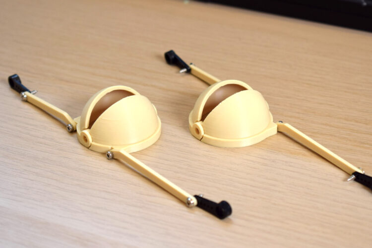
- In this project: The inside of the eyelids may have overhangs, requiring sanding for smooth movement.
Materials
13 items- As needed 3D printer filament (PLA is fine, but use a good brand as some parts are small and fragile. ABS is good for realistic eyes but not necessary.)
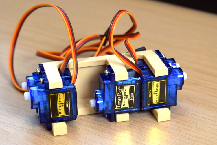
- 6 Micro servos, SG90 (TowerPro SG90 or equivalent.)
- Various Screws, M2 and M3 (Various lengths and head types. Specific sizes mentioned: 4mm, 5mm, 6mm, 8mm, 10mm, 12mm M3 bolts; 4mm, 6mm M2 screws.)
- 1 Arduino microcontroller (Uno, Nano, Mega, or similar.)
- 1 Servo Driver Board, 16-Channel (Adafruit 16-Channel 12-bit Servo Driver or equivalent.)
- 1 Power supply (Around 5V, 4A.)
- 1 Female DC power jack (Corresponding to the power supply.)
- 1 Joystick, 2-axis (Analog joystick module.)
- 1 (optional) Potentiometer (Linear potentiometer for adjusting eyelid openness.)
- 1 Momentary pushbutton (Push-to-make switch for triggering blinks.)
- 1 Resistor, 10kΩ (For the potentiometer circuit.)
- As needed Breadboard jumper wires (For connecting components on a breadboard.)
- 1 sheet Sandpaper (Around 240 grit for smoothing parts.)
Tools
- 3D printer - Required for printing the parts.
- Pin vise hand drill (optional) - Optional, useful for adjusting hole sizes if using an older/less capable 3D printer.
- Screwdriver(s) - To match the screws used (Phillips or flathead as needed).
Instructions (4 steps)
Printing
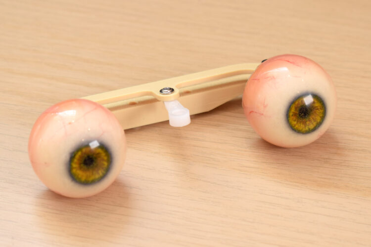
Download the files for printing from the provided link. Print the parts with a healthy printer; no supports should be needed. Use a stronger material like ASA or PETG for thin sections and snap-fits, but PLA works. Use a 0.2mm layer height. The eyes come in options: blank round, iris/pupil cutout, or a highly realistic version. They attach via snap-fit to the eye adaptors. Ensure the eyes are 32mm diameter or less. Sand the inside of the eyelids if needed due to overhangs. Some holes are undersized for direct screwing; others are oversized for rotation. Adjust hole sizes with a drill if your printer isn't accurate.
Test fit parts as you go. Ensure smooth movement by sanding or drilling as necessary.
Measurements
Assembly
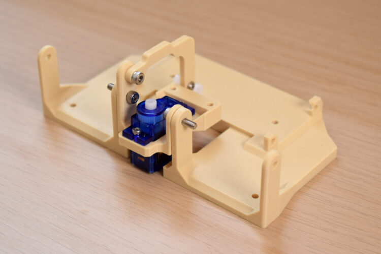
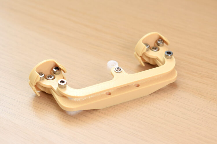
1. Connect the two bases with 10mm or 12mm M3 bolts. This pivot is for y-axis motion and eyelids. 2. Place the servo in position and screw it in with 4mm or 6mm M2 screws (x-axis actuator). 3. Attach the y-axis arm to the sub-base with a 4/5/6mm M3 screw, and attach a servo horn on the third hole from the center using a 4mm or 6mm M2 screw. Check orientation. 4. Start the x-axis assembly by screwing the forks into the eye-adaptors with 4/5/6mm M3 bolts. The fork holes should be oversized so screws bite into the adaptor. 5. Attach the three-point connector to the top of the forks; the M3 screw will bite into the undersized hole. Attach a servo arm to the center of the three-point connector using a 5mm M3 bolt (drill the servo arm hole to 2.5mm–2.8mm if needed). 6. Attach the eye center-link to the eye adaptors with an 8mm M3 screw, ensuring the flat surface faces up and the sloping section faces down. Plug in the eyes. 7. Screw this assembly to the center of the sub-base with two 12mm M3 bolts. 8. Load the servo block with five TowerPro SG90 servos in the correct orientation. Attach it to the base with four M3×10mm bolts. 9. Identify eyelids using the photo. Connect the relevant connector with a 4mm or 6mm M2 screw, and attach a servo arm to the other end using the last hole in the servo horn (drill to 1.5mm–1.8mm if needed). 10. Attach the eyelids to the base, but don't connect servo horns yet.
Manipulate the assembly regularly during build to ensure smooth movement without friction.
Measurements
Wiring, Code, and Finishing Up
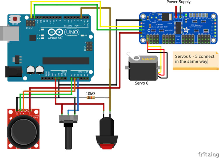
1. Upload the code to the Arduino. Wire everything up. Refer to the Adafruit guide for setting up the servo driver board if needed. Download the Adafruit Servo Driver Arduino library. 2. All servos should now be powered and in their neutral position. Link all servo arms to the servos with the eyes facing straight forward. You can plug them in while powered, then disconnect power to screw them in properly. The y-axis servo arm position may be awkward; if it doesn't hold, consider removing an eyelid servo to screw it in. 3. Test motion with the joystick to ensure no issues. 4. For eyelids, attach the servo arms while they're in the blinking position to align all four in the center. Do this by holding down the blink switch or creating a short circuit over it. Once aligned, pop a screw in to secure them.
Testing at this stage helps catch any mechanical issues before final assembly.
Operation and Integration
Your model is complete! Use the joystick to control eye direction; eyelids move subtly with the gaze. Press the button for a rapid blink. The potentiometer adjusts eyelid openness at rest for a sleepy or alert look. To integrate into larger projects, swap joystick, potentiometer, and button inputs for signal cables from your controller. Control direction with analog signals through pins A0/A1, openness from A2, and send a high/low digital signal for blink.
There are extra pins on the Arduino and driver board to add more animatronic parts.